Presentation
The Ascii Graphic Database System (AGDS) format is an ascii (text) version of the wellknown and industry standard GDS II binary format. This format hierarchicaly represents geometric shapes, labels and other layout informations (see http://en.wikipedia.org/wiki/GDSII for more informations).
The ascii format has several advantages versus binary format:
- human readable,
- easy to edit manually or with dedicated tools,
- easy to search or grep into,
- easy to compare and understand differences between two files,
- easy to convert.
The conversion from Ascii GDS to binary GDS and vice versa can be done with OwlVision GDSII Viewer available at http://owlvision.org
Since it has been developped in java, it can be run on all platforms.
Author
Damien Dupuis: damien.dupuis(at)lip6(.)fr
Limitations
Currently the only supported shape in this driver is the rectangle.
Stand alone database structure
The database conists in for simple objects :
- AGDS::Library contains all AGDS library informations such as the name, the units used (user and physical) and the list of all Structures.
- AGDS::Structure describes a GDS Structure with a name and a list of Elements.
- AGDS::Element is an abstract class from which derived the AGDS::Rectangle.
- AGDS::Rectangle describes a rectangle element of a structure.
Using the driver
To drive an AGDS file, user has to create one AGDS::Library and add AGDS::Structure objects to it with the AGDS::Library::addStructure() method. Each AGDS::Structure contains at least one AGDS::Element added with AGDS::Structure::addElement() method.
All objects can be independently created as far as they are correctly added to their parent.
Once the library is completely specified, simply call the AGDS::Library::writeToFile() method to drive the database to file.
Examples
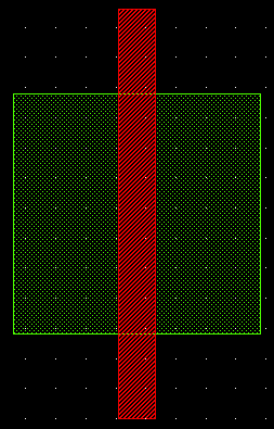
As said is the global presentation, VLSI SAPD project provides C++ libraries and Python modules for each supported format. In this section we present two simple code examples to drive a AGDS file using C++ or Python. These two examples drive the same file transistor.agds:

C++
Here is the C++ code (driveAgds.cpp) used to generate the transistor.agds file. (Source is available in examples directory).
- Note
- In order to compile this code, a CMakeLists.txt file is provided. User must set the $VLSISAPD_TOP variable before running these commands in the directory containing the CMakeLists.txt file: %> mkdir build; cd build%> cmake ..%> make
Python
Here is the Python code (driveAgds.py) used to generate the transistor.agds file. (Source is available in examples directory).
- Note
- In order to run the
driveAgds.pyscript, user must ensure that $PYTHONPATH variable points to the directory containing AGDS.so module.